Snapping a network on to a reference network — a common issue in a GIS
• • •
Polyline network snapping tool?
How does it work in practice?
The problem highlighted here is widespread among many GIS users:
I did retrieve a linear dataset but it was poorly digitized. It does not match other datasets used as a reference, such as a road network for example.
The “manual” solution — going through all the polylines and re-aligning them one by one, maybe point by point — can be extremely time‑consuming, especially when dealing with tens of thousands of points.
Using the snapping tool
The tool POLYLINES ⇒ Network processing ⇒ Network shimming was designed to address this problem
The example shown here applies to a polyline layer representing tourist itineraries. The goal is to align the itineraries to a road network, here the IGN BDTopo dataset.
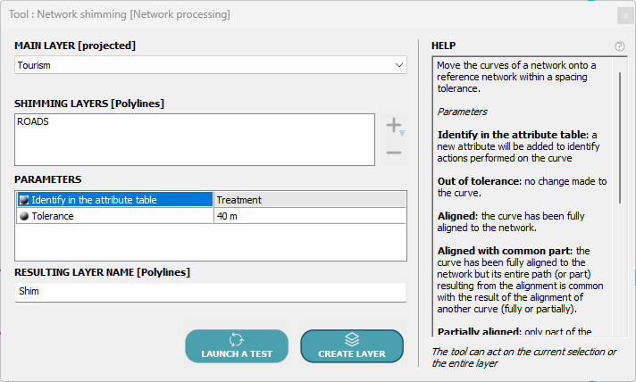
The tool appears as follows:
Simple configuration: choose the layer to be snapped, the name of the resulting layer, and provide two parameters, namely:
- Tolerance: this is a distance in meters that allows the snapping.
- Identifier in the attribute table: the name of a field that will be added to the created layer to record the snapping quality of each polyline.
Principle:
- the parts of a polyline that are at a distance from the reference network smaller than the tolerance value will be snapped onto that network.
- Other parts of the polyline will not be modified, and the shape of the polyline will be adjusted so that the connection between snapped and non‑snapped parts is as consistent as possible with the original shape
Moreover, the tool prefers to move the nodes of the network being snapped onto nodes of the reference network.
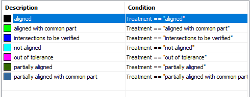
Depending on the data quality, particularly complex cases may be encountered. To highlight them, an attribute is used to describe the “quality” of the snapping.
Six possible values are used:
- aligned
- partially aligned
- aligned with common part
- partially aligned with common part
- intersections to be verified
- not aligned
- out of tolerance
1- Aligned result
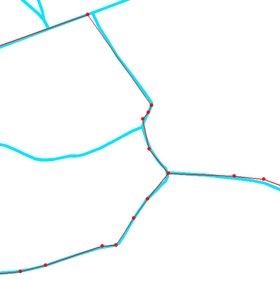
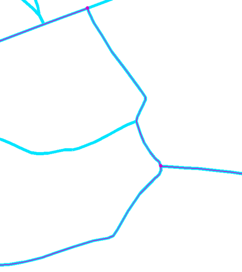
The created polylines are fully aligned. Please note that the topology of the layer to be snapped has been preserved because the ends of two adjacent segments were moved to the same position, by snapping them onto the nodes of the reference network.
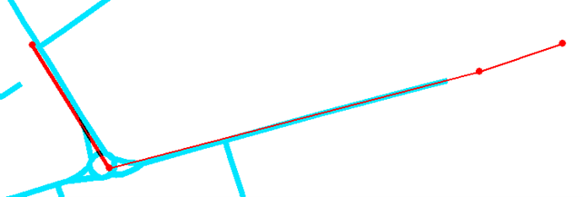
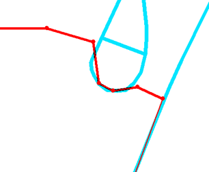
Here is our starting graph. The reference network is shown in blue and the layer to be snapped in red with its points highlighted:
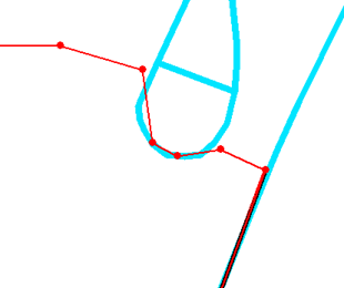
And here is the result: the reference network is shown in blue and the snapped layer in red with its points highlighted:
2- Partially aligned result
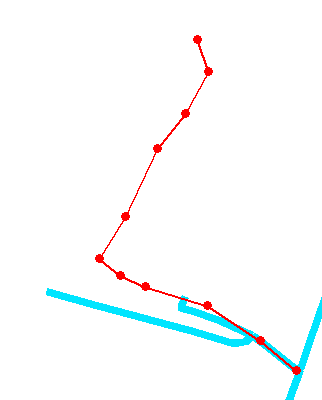
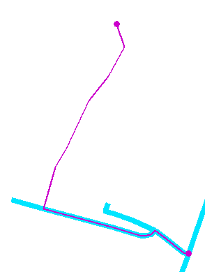
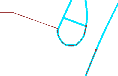
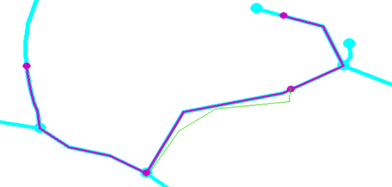
Here, the polyline has certain parts that cannot be snapped simply because there is no nearby reference network, or because some parts lie beyond the tolerance, which yields the following result:
The polyline has been modified by snapping as much as possible to the reference network while choosing the simplest path.
3- Common part result
The operation can sometimes cause the snapping of two polylines to produce two new polylines that partially overlap. This is clearly visible in the following example.
Here we have two polylines whose endpoints meet at a point that is also close to a node of the reference network. The two following images highlight the two polylines respectively:
(Note that the second one will not be able to be snapped on its right part)
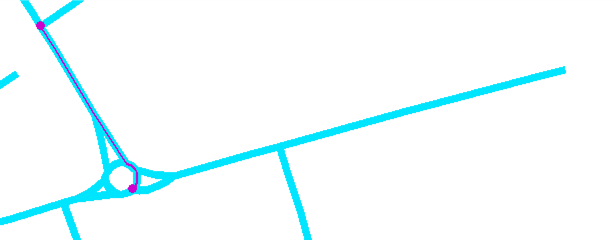
Snapping result for the 1st polyline:
Snapping result for the 2nd polyline:
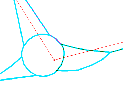
The two resulting polylines both lie on the same portion of the roundabout. It is the most appropriate path for each of them and ends on a node of the network, which becomes obvious when zooming in on that area:
Since the first polyline could be snapped over its entire length, it was labeled aligned with common part, whereas the second, which could not be snapped on its right side, was labeled partially aligned with common part.
Thus the user can identify this case and make the necessary corrections.
4- Intersections to be verified
The tool processing attempts to respect several constraints, in particular moving the endpoints of polylines to be snapped onto the nodes of the reference network, while also staying as much as possible supported by that network.
These directives can conflict in some cases, and the tool will highlight the chosen result by marking the affected lines as intersections to be verified.
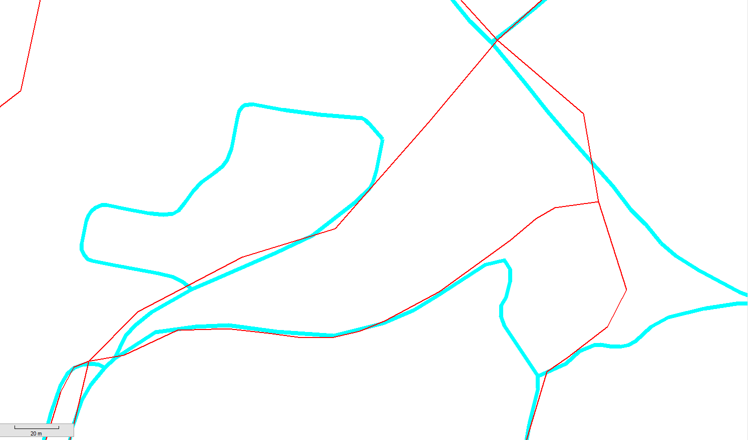
In the following example, we again have two lines to snap whose endpoints touch themselves at a point, as shown in the images below:
First polyline on the left:
Second polyline on the right:
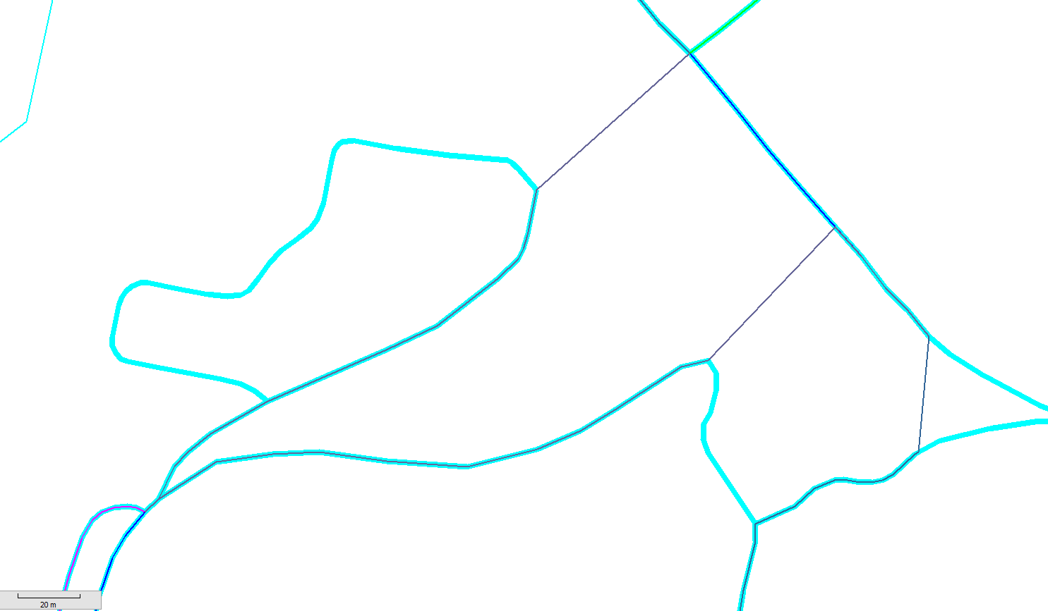
The algorithm will favor staying on the reference network, and the tolerance parameter value causes the left resulting line to snap to the next node.
Meanwhile, the endpoint of the right line being too far from network nodes, it is only snapped onto the network segment.
We thus have two polylines that once shared endpoints but no longer do so after snapping.
To allow the user to identify this case, the two snapped polylines are labeled intersection to be verified.
5- Not aligned
This case occurs when a polyline can be aligned or partially aligned but the resulting geometry is entirely covered by another snapped line.
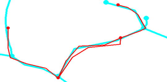
The following example helps explain this case. We have a reference network shown in blue and a layer to be calibrated shown in red, both with endpoints highlighted:
Four polylines to snap can be seen, with joined endpoints, the two central ones forming a loop:
Snapping would be expected to compute the same resulting polyline for these two, but that is not correct and is hard for the user to spot.
The operation will therefore snap the one of the two that is closest to the network.
The other will not be snapped; only its endpoints will be modified to align onto the found network nodes.It will then be labeled as not aligned, and the result will appear as follows:
The aligned polylines are shown in blue and the not aligned one in green.
6- Out of tolerance
Polylines to be snapped whose distance to all curves of the reference network is greater than the tolerance will simply be copied into the created layer and labeled as out of tolerance so they can be identified.
Final result
As a summary, the tool corrects the layer for the vast majority of cases and clearly highlights the few problematic cases to allow for their editing.
